- Definition of a motion transformer
- Motion transformer types
- Focus: Rack & Pinion
- Focus: Crank & Rod system
- Quiz
- Glossary
Overview of motion transformer types
The following section introduces some examples of mechanical transformers and highlight their advantages and disadvantages.
Screw & Nut
The screw and nut system allow to transform a rotational movement into a translational movement by combining the movements of a screw and a nut.

Screw and Nut
Source: https://quizizz.com/admin/quiz/5f17c374c1a99b001b506a90/bolt-nut-assessment
Advantages: This mechanism allows to exert important forces and pressures. It also allows for fine adjustments.
Disadvantages: This mechanism generates a lot of friction.
Its fragility can lead to guiding problems.
The system is slow unless it has a large screw pitch. Example: Jack, vice-grip…
Rack & Pinion
The rack and pinion system transforms the rotational movement of the pinion into a translational movement of the rack or vice versa.

Rack and Pinion
Source: https://www.indiamart.com/supertekengineers/industrial-gears.html
Advantages: There is no slippage during the transformation of this movement. The strength of this system is relatively high.
Disadvantages: The gears that are used may require extensive lubrication as there is a lot of wear.
This mechanism requires precise adjustment because of the teeth between the wheel and the rack.
It is not a cyclic movement; it is a finite movement (you must stop when you reach the end of the rack).
Use cases: Car steering, net tensioners (badminton net for example), adjustment mechanisms of some microscopes, camera tripods, etc.
Crank & Rod system
The crank and connecting rod system transforms rotary motion into reciprocating motion (straight back and forth) and vice versa.

Crank and Rod system
Source: https://technologystudent.com/cams/crkslid1.htm
Advantages: This mechanism can operate at high speed.
Disadvantages: There is a lot of friction due to the many joints in this system. This requires a lot of lubrication.
Use cases: Petrol engines, diesel engines, pumps, medical respirators, steam locomotives, old sewing machines, spinning wheels, grinding wheels, etc.
Cam & Roller System
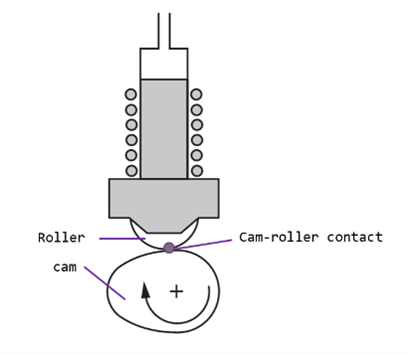
The cam and roller system (also known as the cam and push rod system or guided rod) transforms the rotational movement of the cam into a reciprocating movement of the push rod.

Diagram Cam and Roller System
Source: https://www.tribonet.org/news/testing-of-cam-roller-follower-systems/
Advantages: The cam can be configured to vary the movement of the rod from one translational motion to another.
There is no slippage, the speed ratio is constant.
This system allows a considerable reduction in speed.
Disadvantages: The rod must be guided in translation.
A return spring is usually required to allow the rod to rest continuously on the cam.
There is a risk of severe vibration if the cam rotates at high speed.
Use cases: Mechanical toys, mechanisms for controlling the opening and closing of valves in a car engine (camshafts and valves), sewing machines, etc.
Comparison of motion transformer types
| Advantages | Disadvantages | Characteristics | |
|---|---|---|---|
| Screw & Nut | -Allows important forces and pressures -Used for fine adjustments | -Generate friction -Can lead to guiding problems | Efficiency: ++ Speed: ++ Stability: +++ |
| Rack & Pinion | -No slippage -High strength | -Required fine adjustment -Finite movement | Efficiency:+++ Speed: ++ Stability: ++ |
| Crank & Rod system | -Operation well on high speed | -Poor efficiency (due to friction) | Efficiency: + Speed: +++ Stability: +++ |
| Cam and Roller System | -Constant speed ratio -Can lower the system’s speed | -Rod has to be guided -Risk of vibration at high speed | Efficiency:+++ Speed: + Stability: + |


